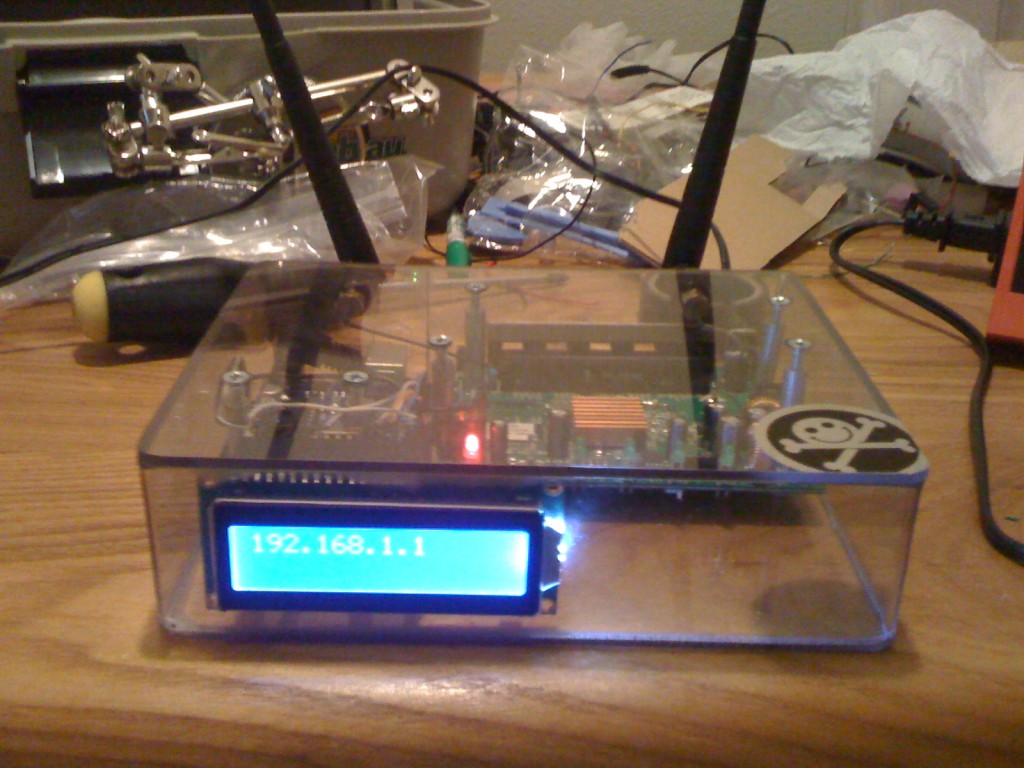
I got a chance to work on and (mostly) finish the Router Arduino project last night. I didn’t get to add anything extra like cool LEDs or anything but I did get the power to the Arduino and the Serial wired up. I still don’t have it doing anything cool yet but hopefully I can whip something cool up on the flight down there.
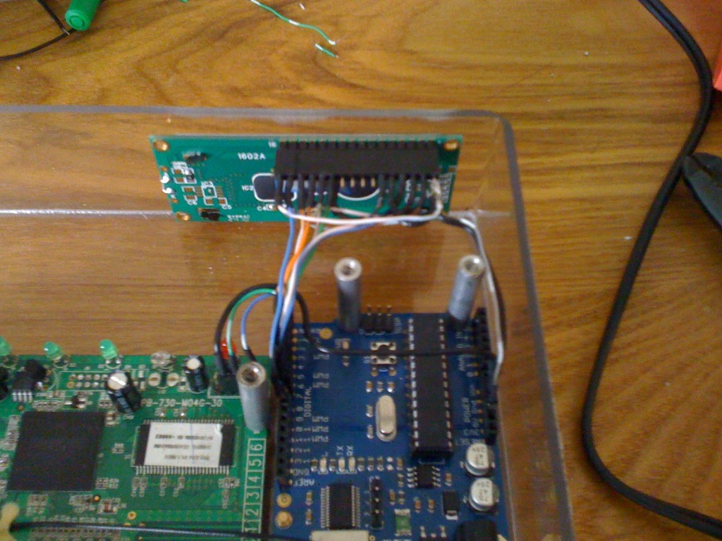
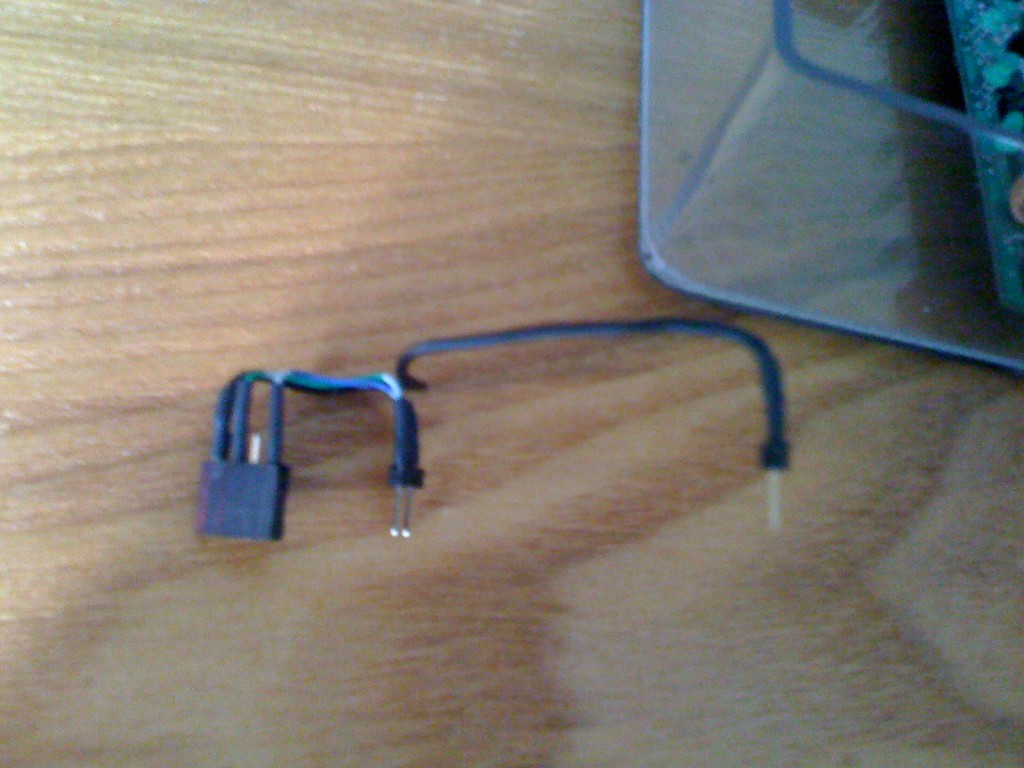
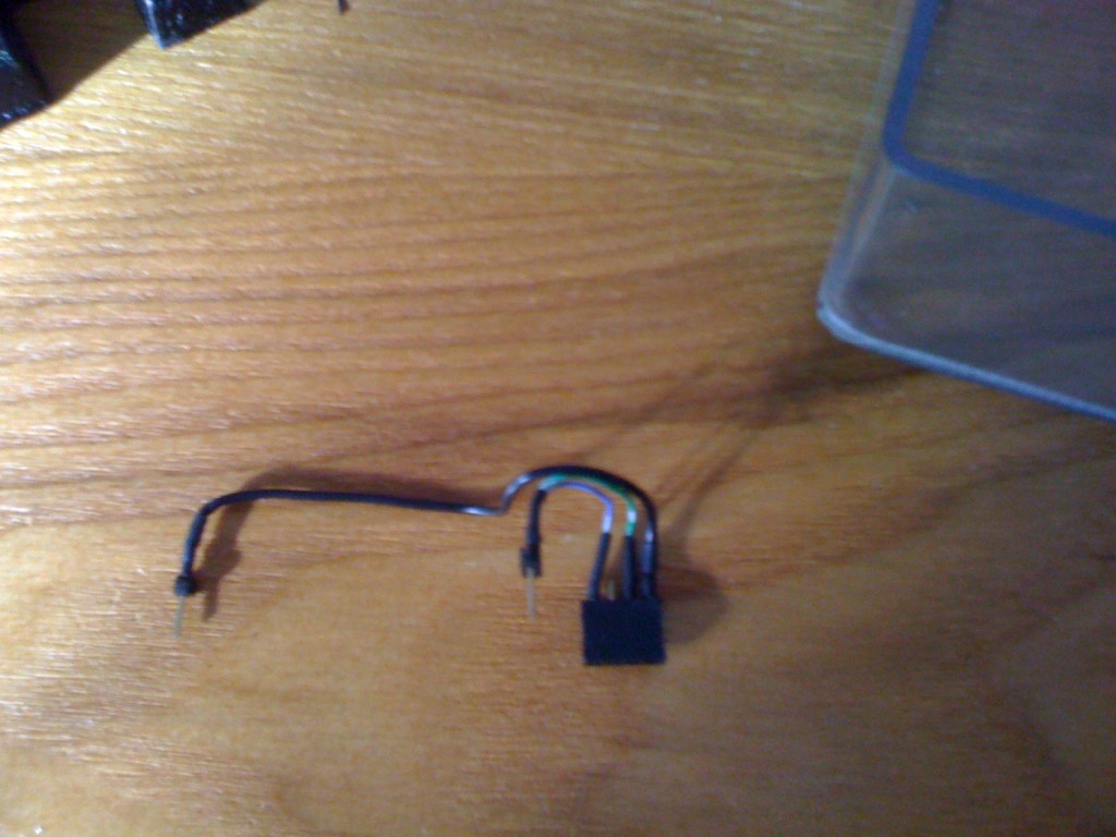
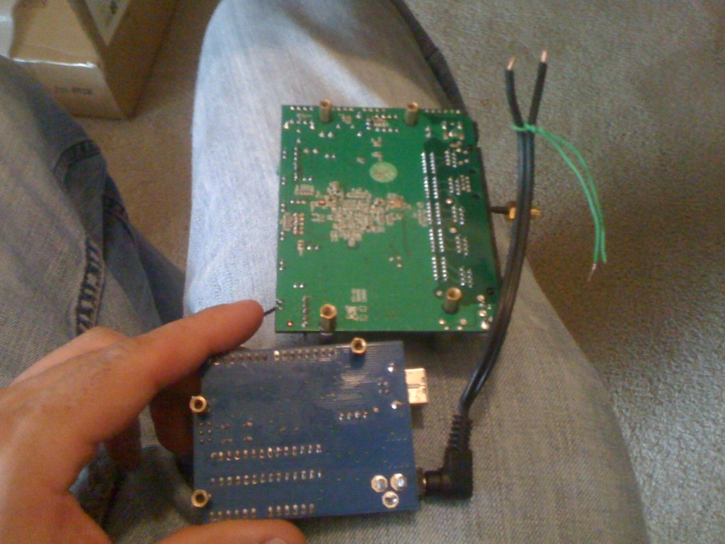
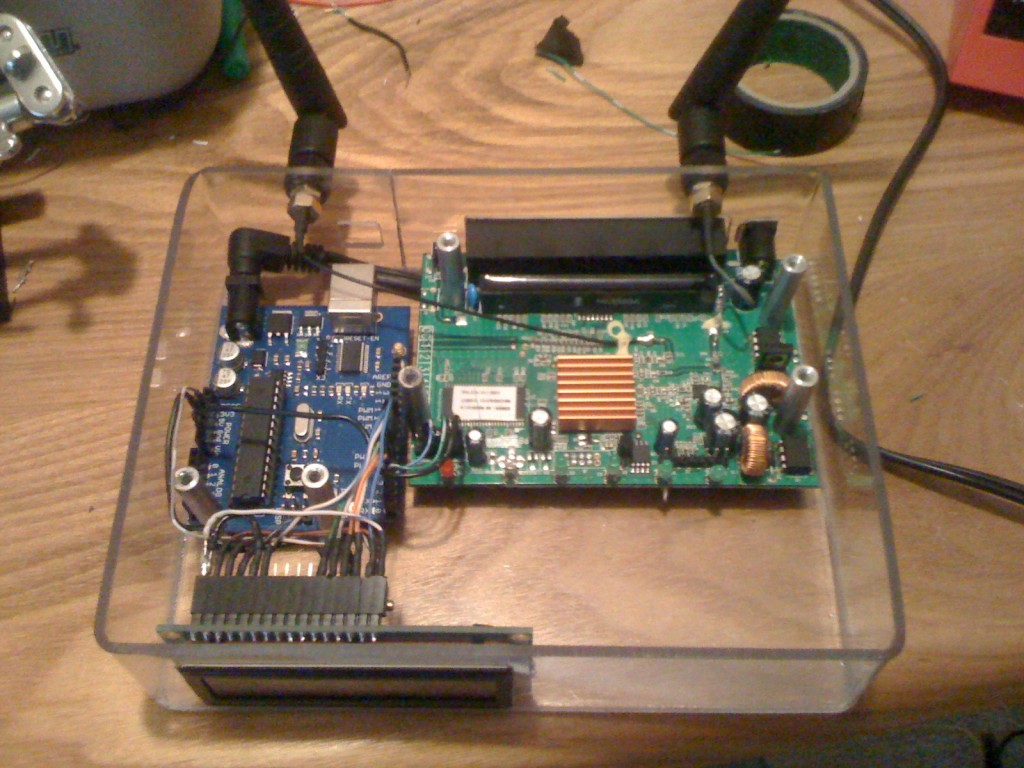
First I want to show the serial harness. I do have to say, I was a fan of the solid core wire for this project. It makes it almost like clay in the regard that you can mold and shape it however you want. The Serial Harness talks TTL from the Router to the Arduino. It uses a GND, Tx, and Rx on the router to go to the respective places on the arduino.
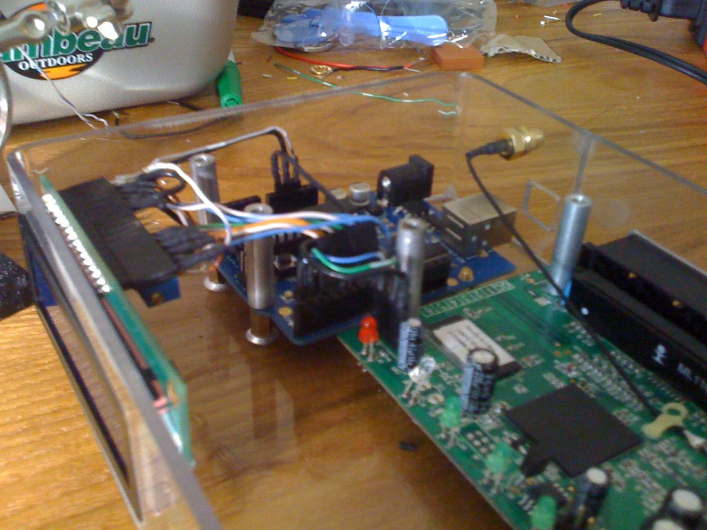
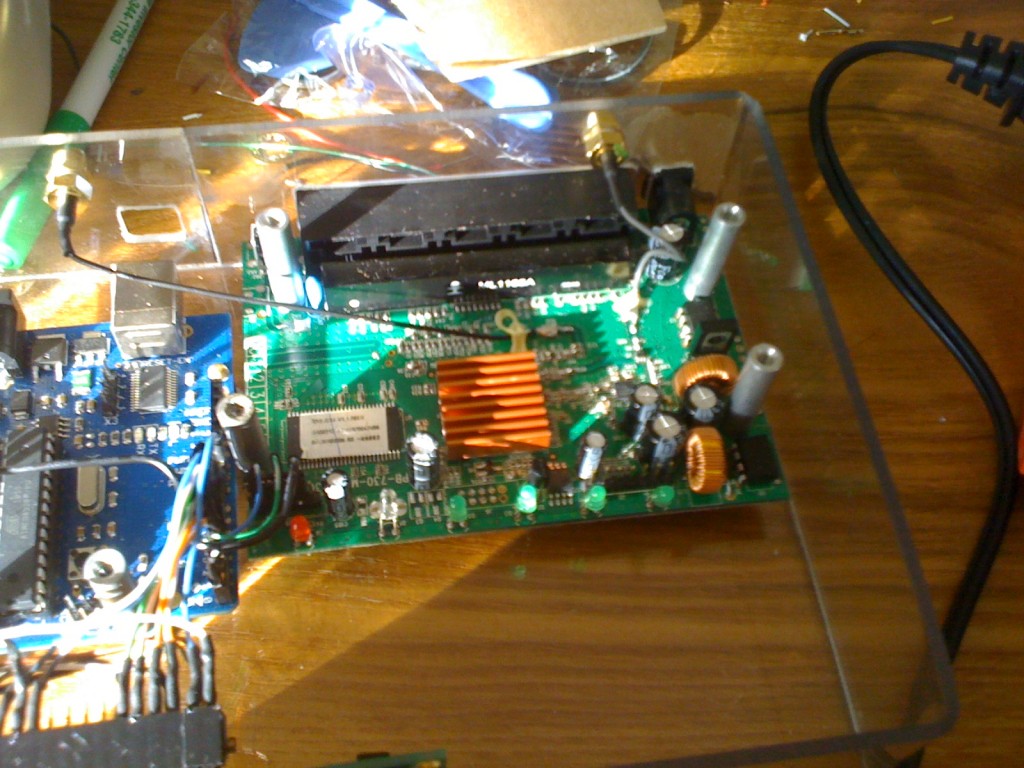
Here it is installed.
Here it is not installed.
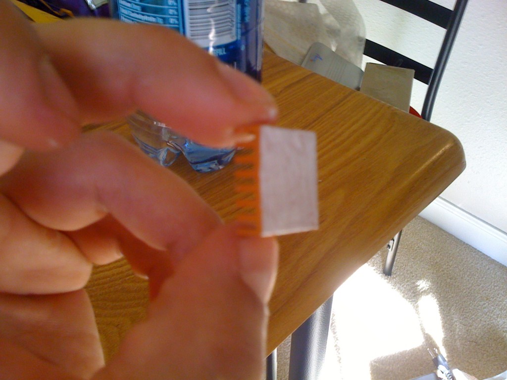
Next I went ahead and applied a heatsink to the broadcom chip. I haven’t overclocked it yet but that doesn’t mean I won’t. In any case it seems to work quite well. (unless I do the USB mod)
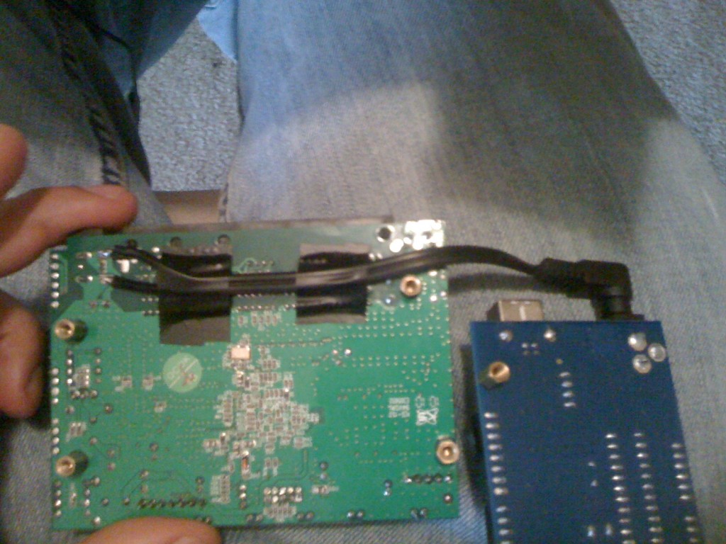
Some people might have been wondering why I designed this with the arduino to sit so far back in the case instead of setting it flush to the back like the router. Well I needed to snag some power from the router and I had an old power cord that didn’t work with a 2.1” jack on it. So I decided to use that to power the arduino. The power to the router is 9v and 0.7a. I was a little worried that the amp draw might be too much for both devices but it seemed to work OK. Since the power cord didn’t work I had to get out a volt meter to test it and find the positive and negative sides. The green wire temporarily tied around was to help me remember which side was positive. I then Had to find a 9v lead and a GND off the board so tap into. I figure the best place was right by the power input and I found a great spot.
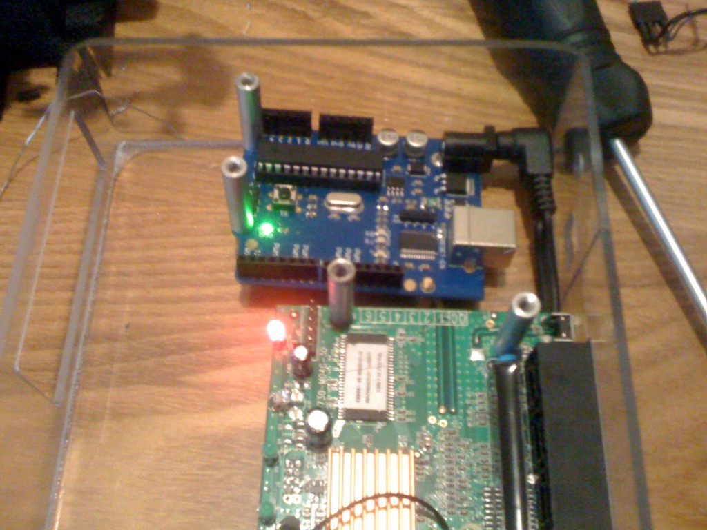
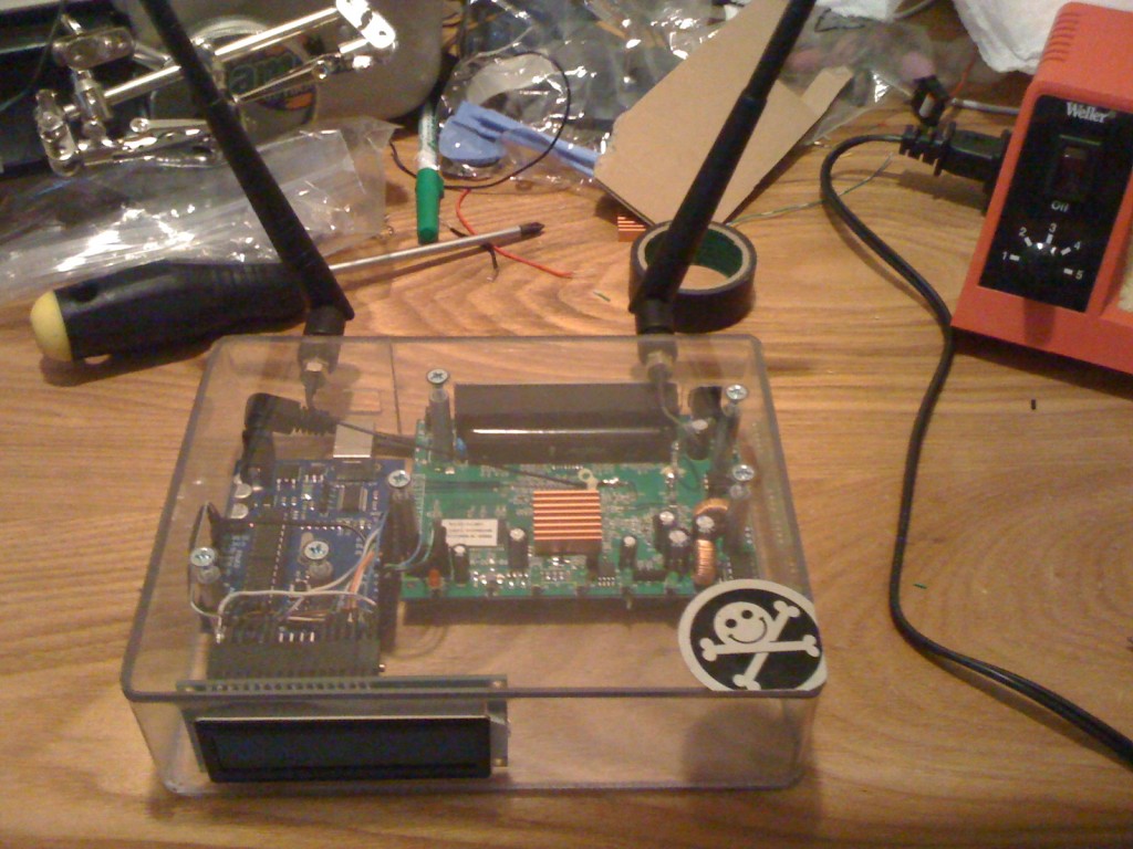
Putting it all back together…
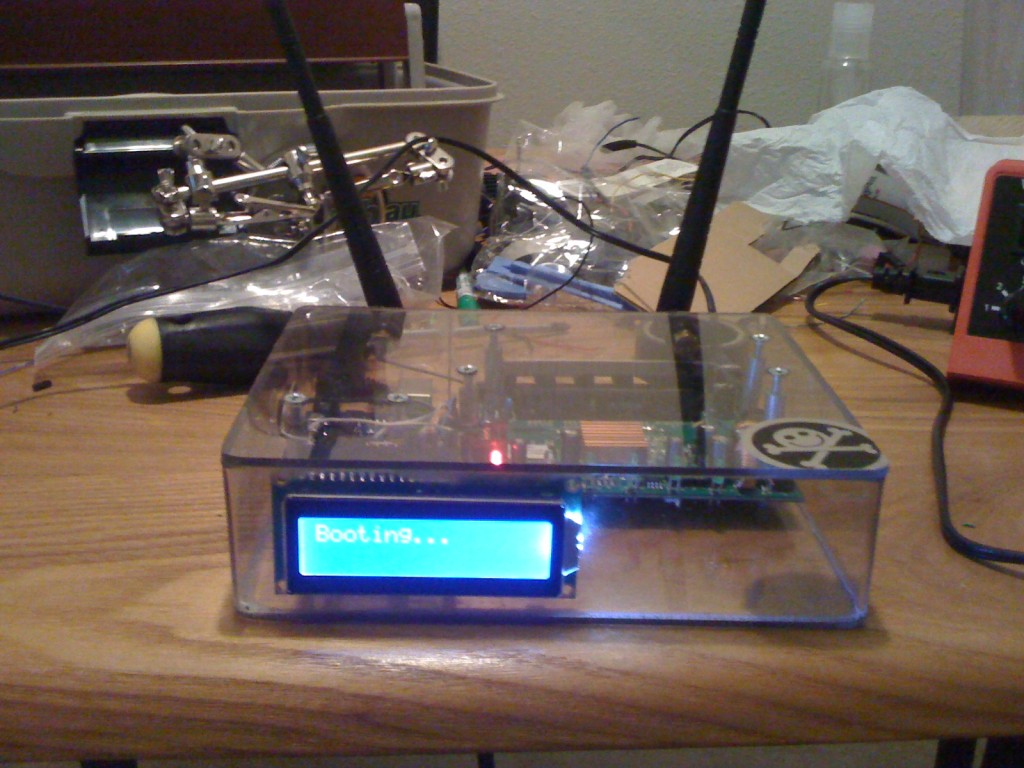
And the Grand Finale…
